
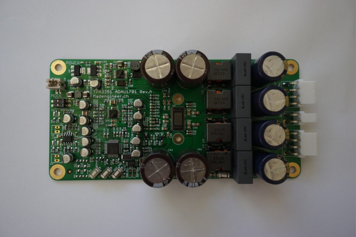
4 Channel DSP Amplifier with ADAU1701 & TPA3251
After having built my first class D amplifier, which is supposed to be a part of a new loudspeaker project, I thought it would make sense to include a DSP as a crossover and equalizer. I could build an active or passive crossover which I did in the past but I felt I needed a bit more flexibility. I went for the ADAU1701 which is well documented and easy to program with the Sigma Studio without writing a single line of code. It has 2 input channels and 4 output channels. The sample rate can be up to 192kHz and the resolution is 24bits which is plenty for my needs.
The amplifier only needs a single supply of 36V. The power supply voltage is converted to 15V by a LM5010 buck converter and then regulated to 12V respectively 3.3V by two LT1117. The 12V are again filtered and power the OpAmps.
The input stage consist of an AC coupled inverting amplifier (OPA1652) with a gain of 6 and a common mode voltage of 6V. The coupling capacitors are 10uF aluminium electrolyte rather than foil because of their size, cost and also footprint constraints. They introduce some low frequency distortion that shouldn’t be audible. (See Small Signal Audio Design, D.Self, P.58 for further explanation). The output signal of the ADAU1701 is filtered with a 2nd order MLF low pass filter (OPA1604/OPA1654/LME49743 just what I had here) and a gain of 2.8, again AC coupled and fed into the TPA3251.
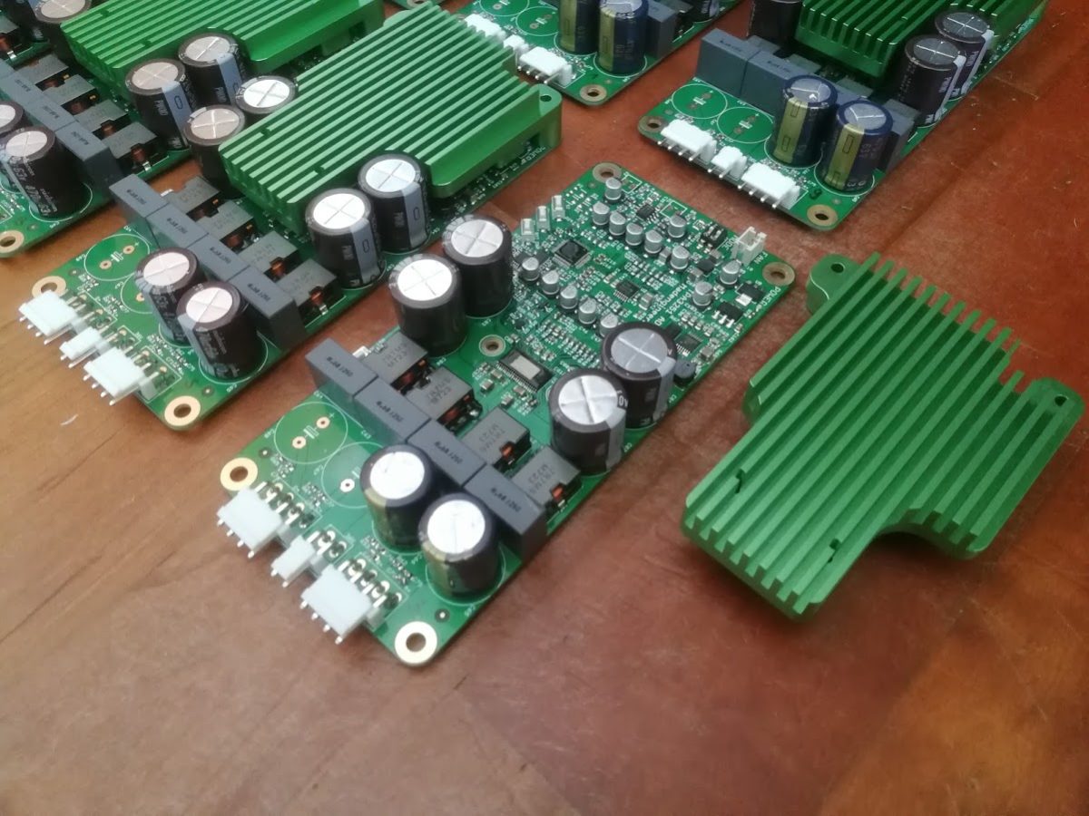
The size of the PCB is 150mm x 72mm with 70um copper. The total dimension will be around 150 x 72 x 22mm.
If connected to the Sigma Studio via their USBi (USB to I2C converter) the ADAU1701 can be programmed in quasi real time from the GUI which makes the development of the crossover a child’s play.
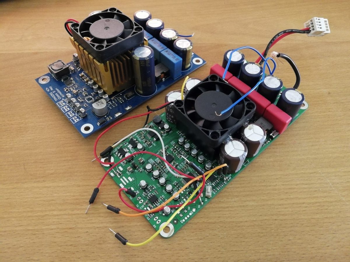
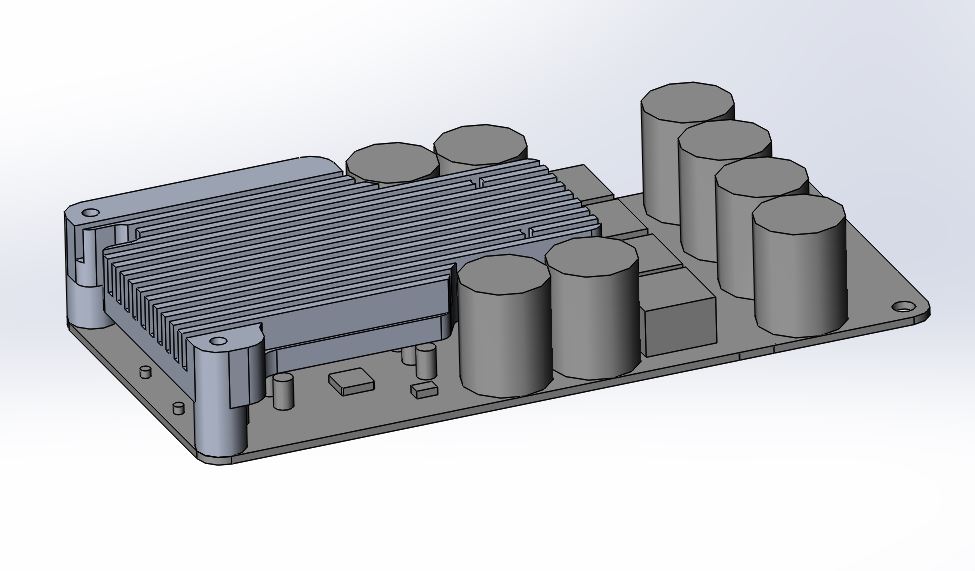
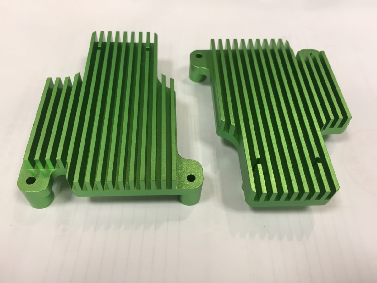
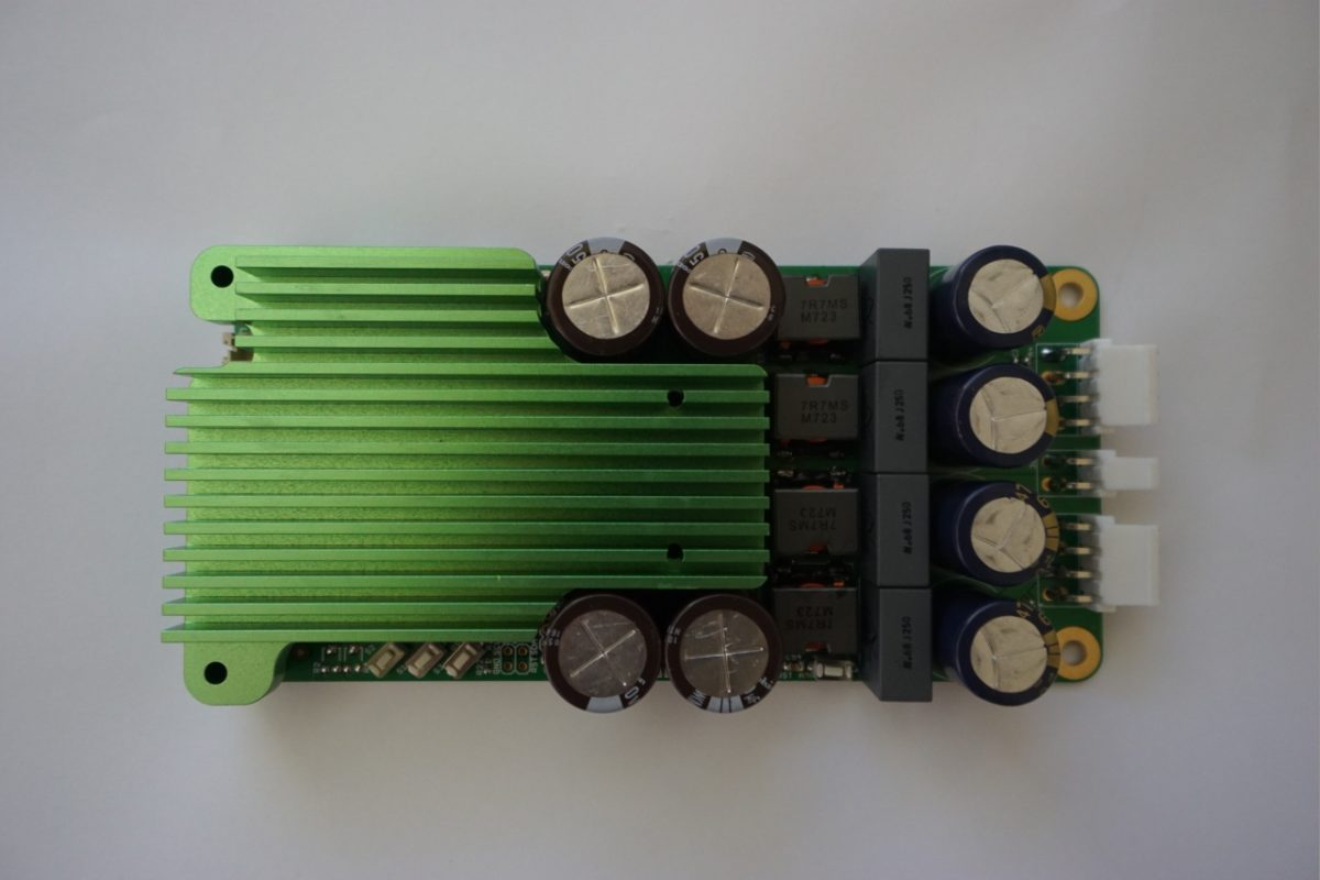
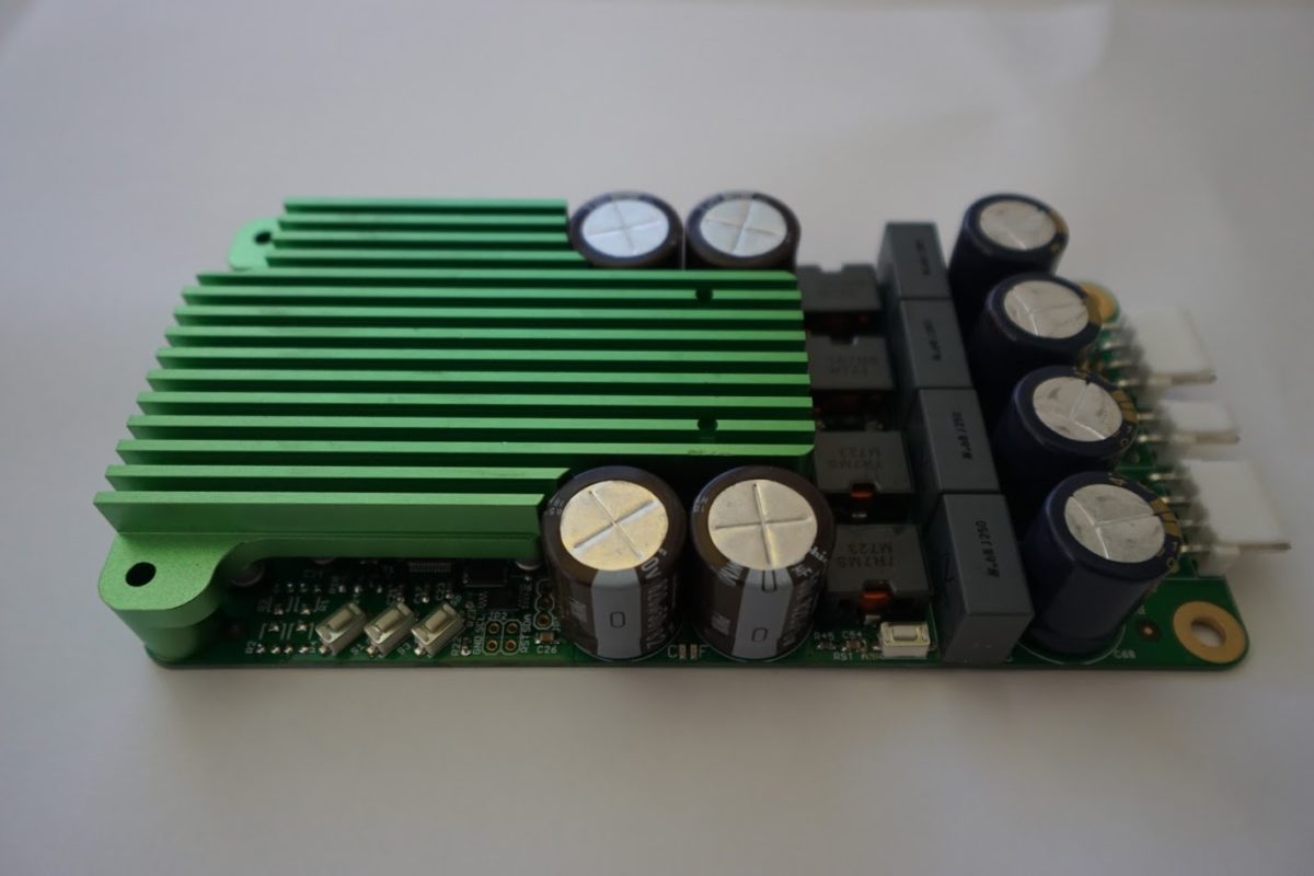
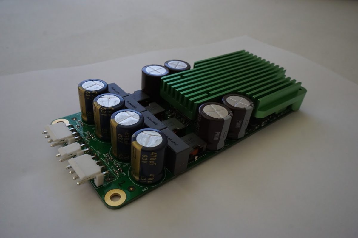
The DSP Amp is a little bit narrower but longer than the amp only module. The heat sink is not the final design, I just used what was laying around. In the final design a custom made heatsink will be installed. I am not yet sure wheter I am going to include a fan or not. I have to test the power dissipation vs. temperature rise with the customized heatsink in normal operation.
With and without DSP
I did some basic measurements with an Analog Discovery 2 I borrowed from a friend. Unfortunately the “Audio Analyzer Suite” from jaxbird on EEVblog forum is no longer available. So I didn’t do extensive measurements on THD etc. The only measurement i did showed a THD of 0.05%@500Hz and 50mV Input which is pretty decent but a bit higher than in the chart in the datasheet. For the measurements the ADAU1701 doesn’t really do anything. The input signal is sampled and then directly routed to the output.
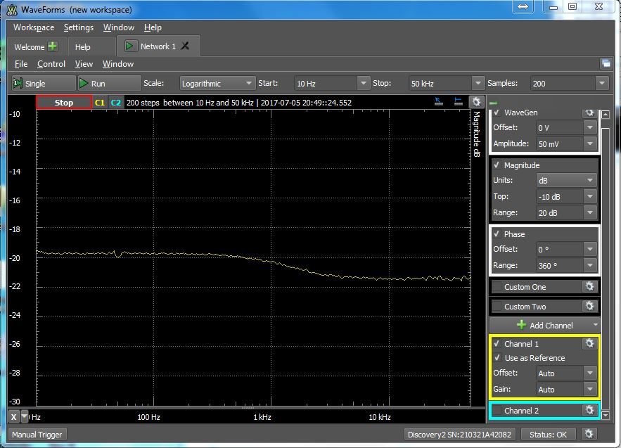
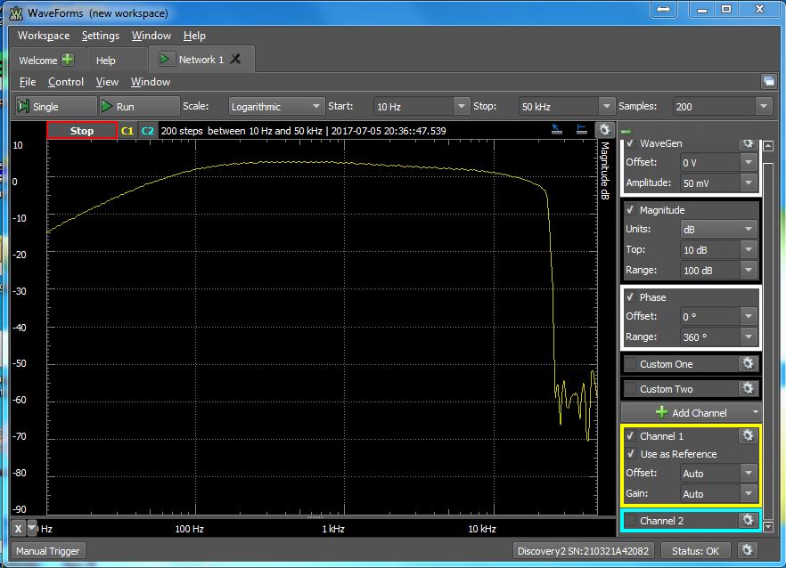
So the first measurement is the frequency response of the Analog Discovery 2. I don’t know why it has a drop of around 2dB at 1kHz, maybe my copy is faulty? Don’t know but don’t really care either, I only wanted to do some quick and dirty measurements.(Edit: Later found out that it’s the cheap probe, forgot to set it to 1x. If set to 1x the attenuation is gone, the following few measurements still contain that error)
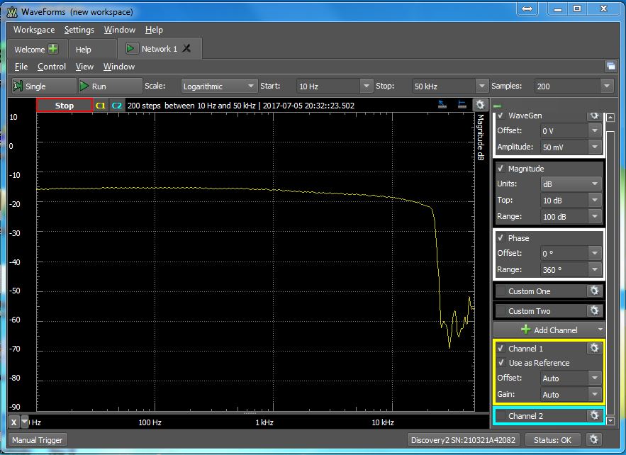
So this is the frequency response after the DSP. The response is mostly flat except for the systematic error the AD2 introduces. Samping frequency is 48kHz.

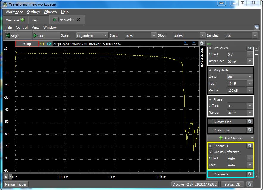
And the response after the MLF filter. I might increase the f-3 frequency a bit. Right now it’s around 18kHz but I want a flat response until around 20kHz, even though I can’t hear it anymore. (I can hear up to 17kHz which isn’t too bad for my age)
After the amplifier without any load.
After the amplifier with a 4.2Ohm load. Notice the frequency drop towards low frequencies: That is because the output capacitor and the output resistor form a high pass filter with -3dB frequency of 86.12Hz. In my case this won’t be a problem and i won’t increase the capacitor value since for low frequency operation it will be used in BTL mode without the output capacitors.
Update:
Later I could get hold of an early copy of the Audio Analyzer Suite which made THD measurements much easier. This is a measurement of the analog discovery 2. Output fed directly into the input. The THD is between 0.01% and 0.02%. I wish it was a bit better but I can work with that. I might invest in a good soundcard to make future measurements. Most modern soundcards have a much better performance to do these measurements. The only “problem” is the small input range which is usually not more than 1 Vrms.
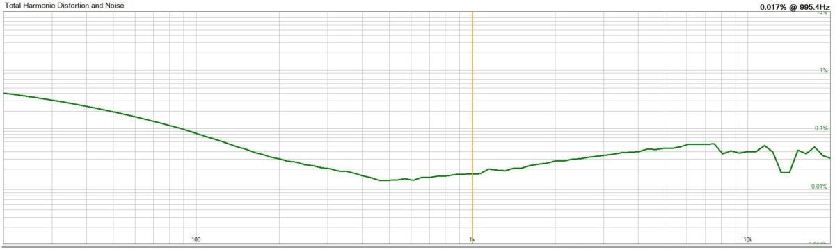
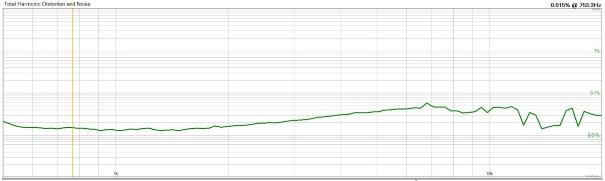
The next picture shows the THD vs frequency of the amplifier. The min THD of 0.011%@8.2R is at around 500Hz which is pretty decent, it could technically be better than that but I wouldn’t know because of the analog discovery. Nevertheless from around 300Hz the THD looks good with a maximum value of 0.055%@7.5kHz. The rise of the THD towards low frequency is due to the value of the input electrolytic capacitors. The amplifier as it is now has a sufficient performance for most applications and one most probably won’t be able to hear a difference to an amplifier with better values.
I couldn’t reproduce the measurements from the datasheet since my equipment lacks the ability to measure a THD below 0.1%. Also my measurement setup is very far from perfect so proper measurements would be even better than the ones I did.
The measurements brought some insight of what could be better. I increased the coupling capacitors from 10uF to 47uF and I will redo some resistor and capacitor values of the low pass filter.
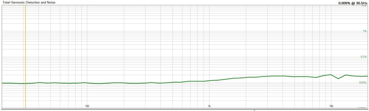
Here’s the measurement with the 47uF capacitor. There is still an increase in THD towards low frequencies but not as “bad” as before. According to the datasheet the curve should be flat. My guess is the increase of distortion comes from the output filter. Any ideas?
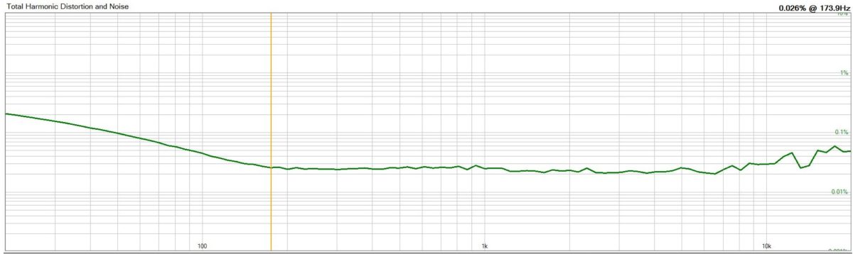
And from 500Hz to 20kHz @ 5W.
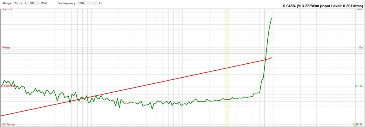
The next measurement show THD vs Power. It doesn’t say too much since I measured single ended but the resistor was driven in BTL mode, also the supply of my PSU was limited to only 25V.
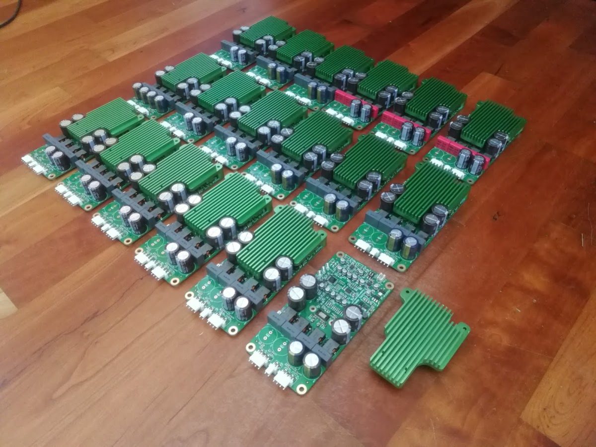
Alright that’s it for now. In the next few weeks I will build a batch of around 25 modules. I also want to have a customised low profile heat sink that is big enough so it can be used without active cooling. It will be manufactured in china.
There might be some things that could be better but I am perfectly happy with the results.
Update 2:
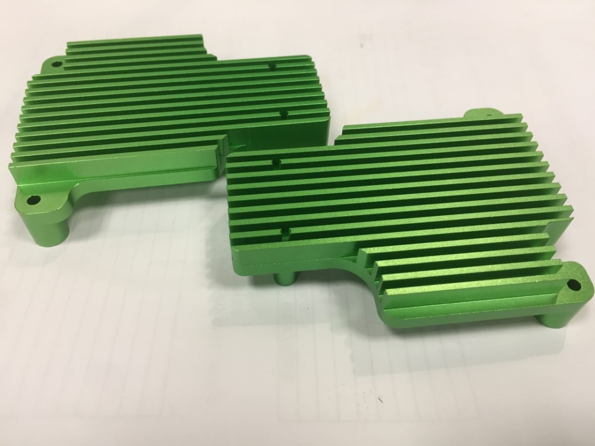
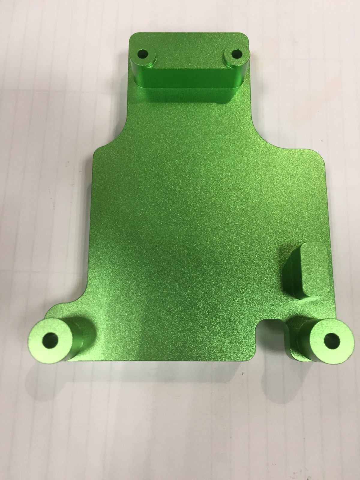
I talked to some manufacturers in China and let them manufacture the custom heat sink. Turned out better than expected and wasn’t really expensive.
Then I ordered all the parts from TME/Mouser/China and started to build a batch. It was quite a tedious work since I placed all the parts by hand. No pain no gain.
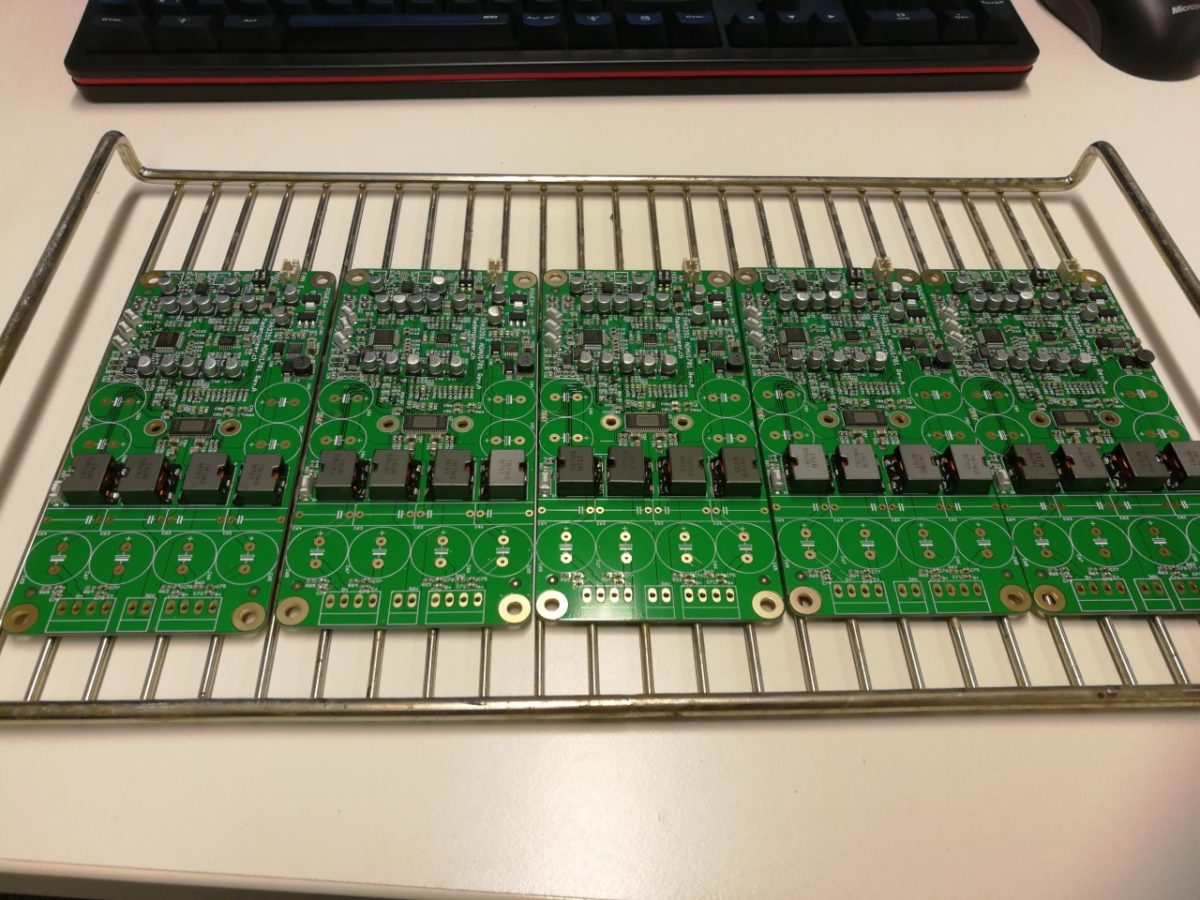
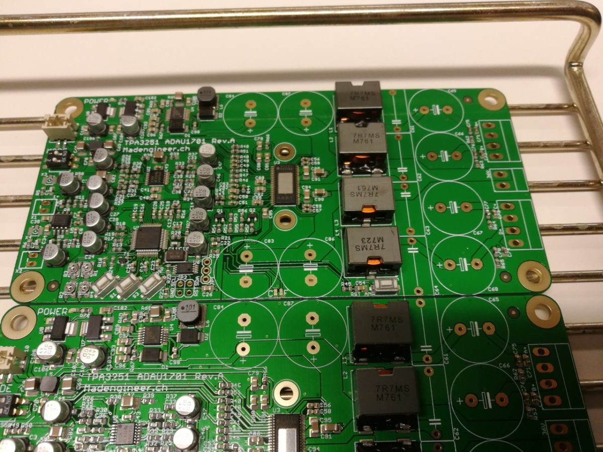
After reflowing and correcting some tombstoned resistors I assembled everything quickly and powered it up. Works like a charm.
Hello,
We are very much interested in your 4 Channel DSP Amplifier with ADAU1701 & TPA3251!
Could you let me know pricing and delivery time?
Great project! Excellent for multichannel application!
Will you sell the unit?
I don’t intend to sell the units this time.
Hi,
Very interistening project !
When you say 4 chanels, does it mean it can be used for 4 ways speakers, one amp per speaker, or only one amp for 2 ways speahers ?
Laurent
Yes it can be used for a 4-way loudspeaker. But I wouldn’t advise to do so, since there is only limited power available when used in SE configuration (depending on the speaker impedance).
A 3-way speaker would be better. 2xSE für the HF and MF chassis and 1x BTL for the LF chassis. I use it currently in that configuration.
Yes, probably not enough poxer for 4 ways…
And did you explain your system somewhere ? I would be very curious to see it.
No, it is not documented online. And I probably won’t document it due to time issues.
Hello Schmiben,
Don’t know if you’ve made all what you wanted to do with your PCB, but if some are not used, I’m very interesting by buy to of them.
Just tell me the price…
Hi Laurent,
I won’t sell the PCBs because I don’t have time to write a proper documentation and provide support. Sorry.
Best, Ben
Hi Schmiben,
Fantastic engineering here, especially like the fit of the custom heatsink. Will you release a schematic of this at all so I could produce my own?
Cheers,
Edd
Do you plan to publish/open-source the gerber/project files? If not, how can I get one of these sweet babies?
Is it well suited for 2 x 2-way Speaker?
Hi Edd and Moritz,
I already sold two units to a guy in Germany and it gave me quite some work to provide support. Therefore I won’t sell any and won’t release any
schematics. Also there’s no real BOM and I would need to create one as well… I don’t really have time for that.
I might do a redesign in the future and make everything open source. There are still some errors in the schematic that i will need to fix. But at this moment
I can’t help you guys. Sorry
Ben
Anything new regarding the redesign and making it open source?
Nope
Any news according PCB or BOM.
I want to build TPA3251 Amp, your design looks more clear.
Hello,
Can you sell your PCB, soldered or unsoldered version?
Sorry I don’t do that. It’s too much support work and I don’t have the time for that. Sorry.