
Neoden4 Review – The good the bad the ugly
Recently I have purchased a Neoden4 for my workplace to have a quicker turnaround for pre production and low volume series. I have no previous experience with professional assembly machines which is probably better since I was already annoyed enough getting the machine properly running without randomly misplacing parts or stopping in general. Nevertheless I learned the quirks of the machine and I am now able to use it as intended in the first place which means placing 0603 parts with very few errors and also placing 0402 occasionally.
TL.DR:
I am happy with the speed, placing accuracy, amount of feeders (remember this is a cheap machine) and rate of misplaced parts.
I am not happy with the programming workflow, the feeders/peelers and the UI. Since I have rarely seen and used an even halfway decent software from China these issues were kind of expected.
Limitations of the machine
The maximum panel size using the conveyor and a JEDEC tray is 140x1500mm. The maximum panel size using the conveyor without a JEDEC tray is 310x1500mm.
The maximum component height is 5mm. Although higher components can be placed, it is not recommended because the toolpath must be defined manually to avoid a collision and the components can only be picked from a tray. It is probably quicker placing these components by hand.
Assembly and first use
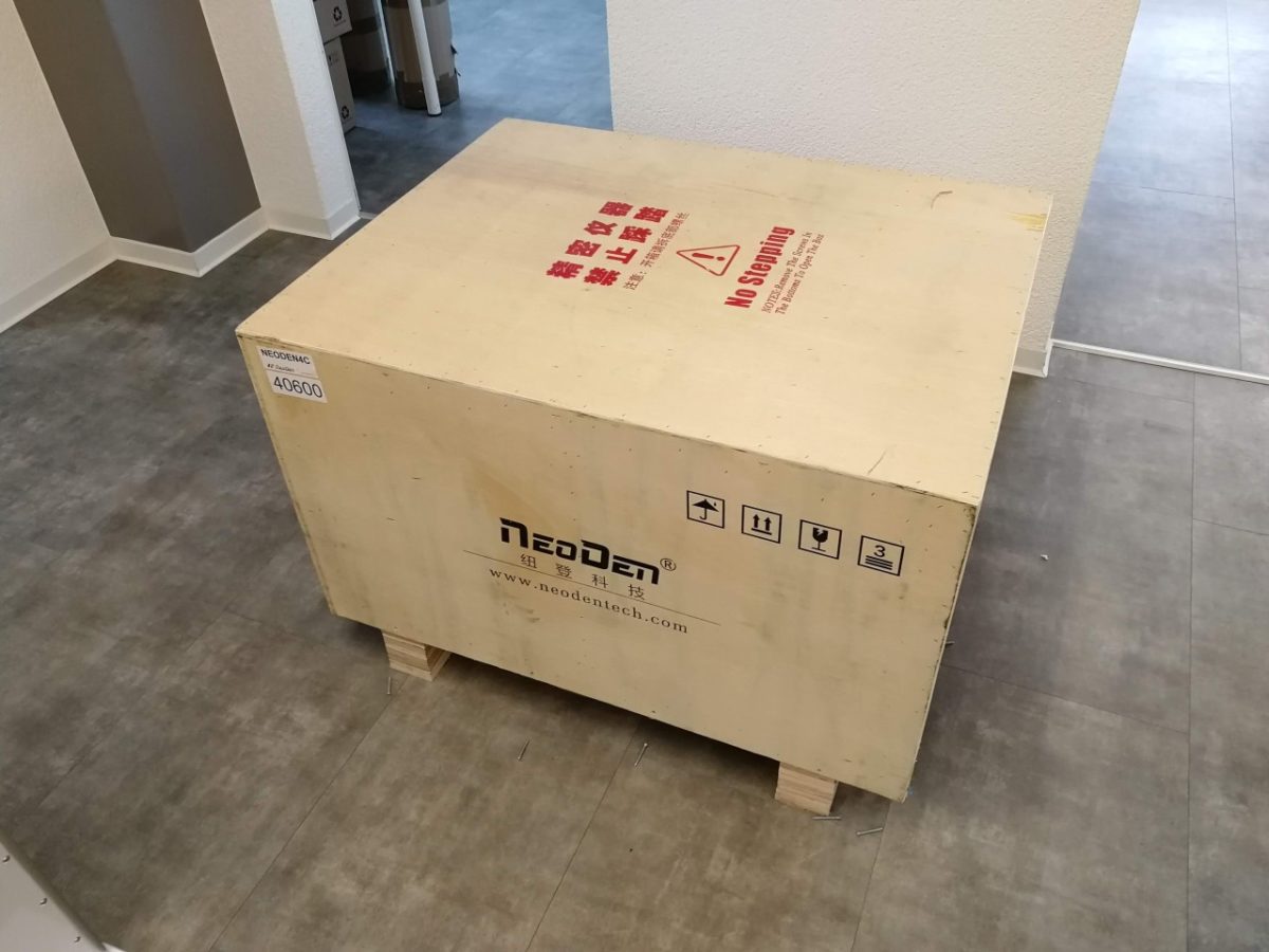
The machine comes safely packed in a wooden box and is attached to the box with vibration dampeners. It is very easy and quick to assemble the stand and the machine.
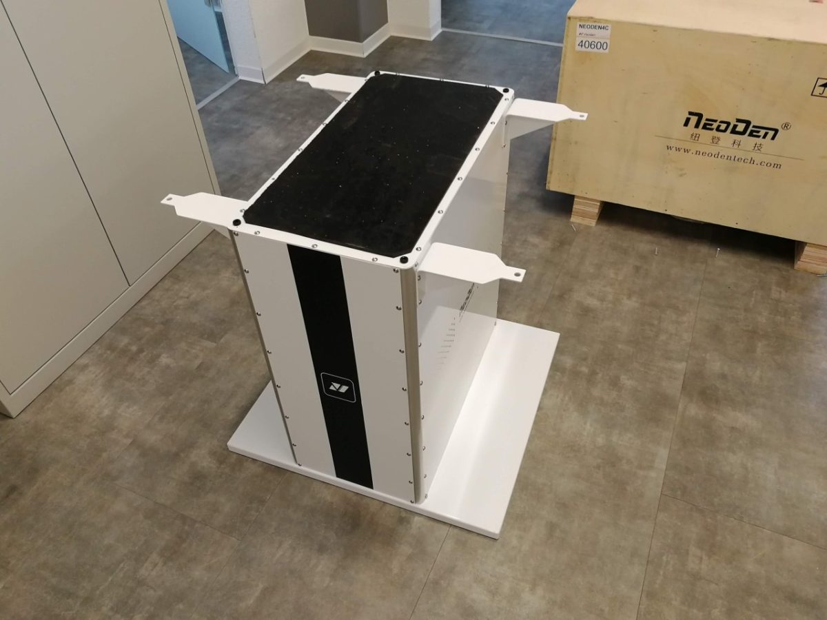
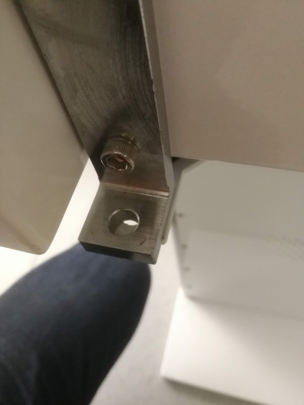
Somehow they either changed the hinges or forgot to provide the necessary spacers since the machine can’t be properly screwed to the stand because the two hole on one side are off by about 1cm. It doesn’t really matter though.
It took me about a day to actually get the first parts placed because the “manual” which describes the machine is pretty much unusable. The part where the programming of the machine is described is way too short and missing most of the important bits. Also I didn’t receive a sample program that could lead me into the right direction. After reading about the programming one some forums -of course I couldn’t be the only person with the same issue – I got it to work. First with an offset / rotation issue…then only offset and finally I got it to work how it should.
How does the programming work?
The first component in the PCB chip list is the reference point for the absolute machine coordinates. All other components, including the fiducials are relative to the first components. Since there is only one reference point, the machine is unable to detect a rotation of a single PCB. Detecting an angle of a PCB or panel is possible.
One needs to determine the travel direction of the PCB before exporting the chip list and adjust the rotation of the PCB accordingly in the CAD program.

- Export the chip list using N4mount.ulp located here: N4_mount This is only to determine the first component in the chip list. Remember the location of the first component on the PCB. If needed rotate the PCB or the panel so the XY coordinates match with the XY coordinates of the machine.
- Insert PCB at point A
- Press Feed. The conveyor transports the PCB and the camera detects the edge of the PCB. There is no need to press the align button in the PCB feed settings.
- Press left bottom align in the panelized PCB first chip setup. Use the camera to mark the center point of the first component in the chip list. If the first component is not suitable as a marking point (e.g. large components) use a different one and make it nr.1 in the chip list. One can also use a fiducial as a first component and then skip it during assembly. Just make sure the first component of the N4mount.ulp and in the chip list are the same.
- Create 3 fiducials in the PCB mark settings window and align the coordinates of the fiducials placed on the left bottom PCB accordingly.
- Important: The PCB needs to stay exactly in this position for the next step. Write down the coordinates of the first component.
- Export the chip list using N4mount.ulp once again and fill in the first component coordinates. Now the coordinates of all components in the chip list are the same as the absolute machine coordinates.
- Export your CSV file from the machine to the USB stick and open it on your computer.
- Copy and paste the chip list from your generated file into the CSV file exported from the machine.
- Import the modified file into the machine. Press the edit button. DO NOT press the feed button or any button that moves the PCB from its current position.
- If there are several PCBs on a panel adjust the rows and columns in the panelized PCB first chip setup
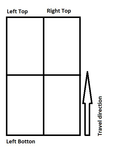
- Mark the center of the first chip of the 3 PCBs left top; right top… Even if there are more than 4 PCBs on a panel the first component of those three PCBs needs to be marked.
- Press the Generate panelized list. You can align every first component of each PCB. If the above steps were followed carefully this usually isn’t necessary.
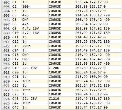
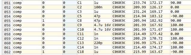
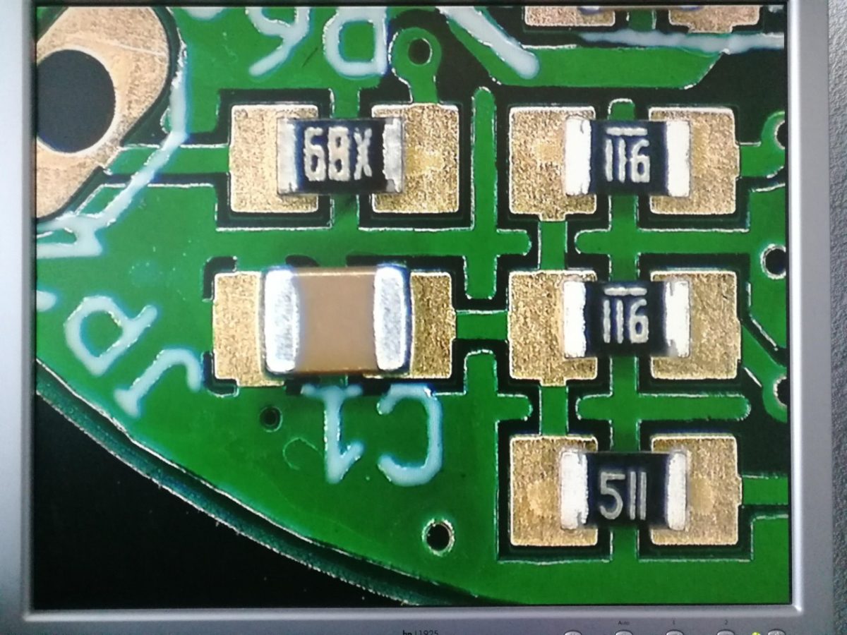
- Fill the feeder settings. The footprint should be entered for parts bigger than 3x3mm. Otherwise the vision system might not properly recognize the real size of a part. See the picture below. But: Since you can’t adjust the camera settings, sometimes it won’t recognize your parts no matter what you do. That’s a very ugly and annoying bug.
- Press align feeder and nozzle. If you don’t do this you will get an error and the whole system will crash. Restart needed. It will also crash when no value is entered.
- Mount the file.
- Step Enter
- Teach the fiducials
- Use vision align and check whether the center of each component is correct. If it doesn’t match – congratulations you can do it all over again. If only one or two components don’t match, you can adjust the coordinates on fly.
It is much easier and quicker to prepare the settings like pick height, place height, feeder and peel box strength, footprint and speed directly in the CSV file.
Fiducials: Should be 1mm diameter and 3mm without solder mask. Smaller fiducials are not properly recognzed. Fiducials must be far enough away form other components in order to avoid misrecognition.
Pick Angle: Before running a real job it can make sense to run a dummy job without solder paste but with sticky tape on the PCB. Run the job normally and correct the pick angles if necessary.
Very shortly after the initial success I was greeted by this gem.
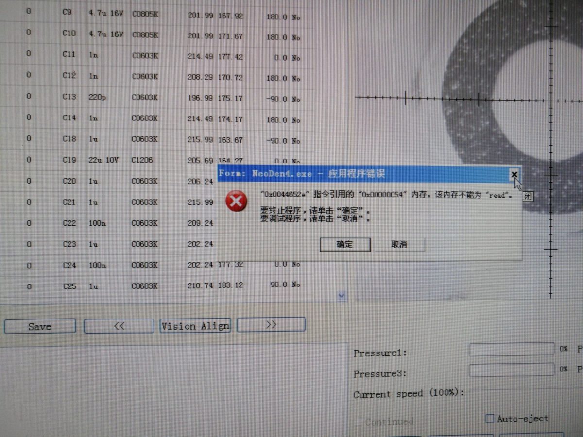
This error can occur in the middle of a running program if you forget one of the following two things: The value field of a component is empty or you forgot to press the “Assign feeder and nozzle” button. Luckily it is possible to resume the placement from the part where the program crashed. (After fixing the problem obviously).
Feeders
When feeding large parts e.g. TO-263 the spring inside the feeder must be removed otherwise it will press against the top of the feeder causing the gear to slip. If the spring is already removed and the gear still slips the best option is to cut the tape in strips and place it on the adjustable tray as seen in the picture below.
I had several feeder jams because smaller parts fell into the small gaps next to the gear. So if a feeder suddenly stops working I check first if the reel/tape is stuck. If it isn’t I dismount the feeder and take it apart. Usually the culprit is found within minutes. It’s still very annoying…but hey you get what you pay for, right?
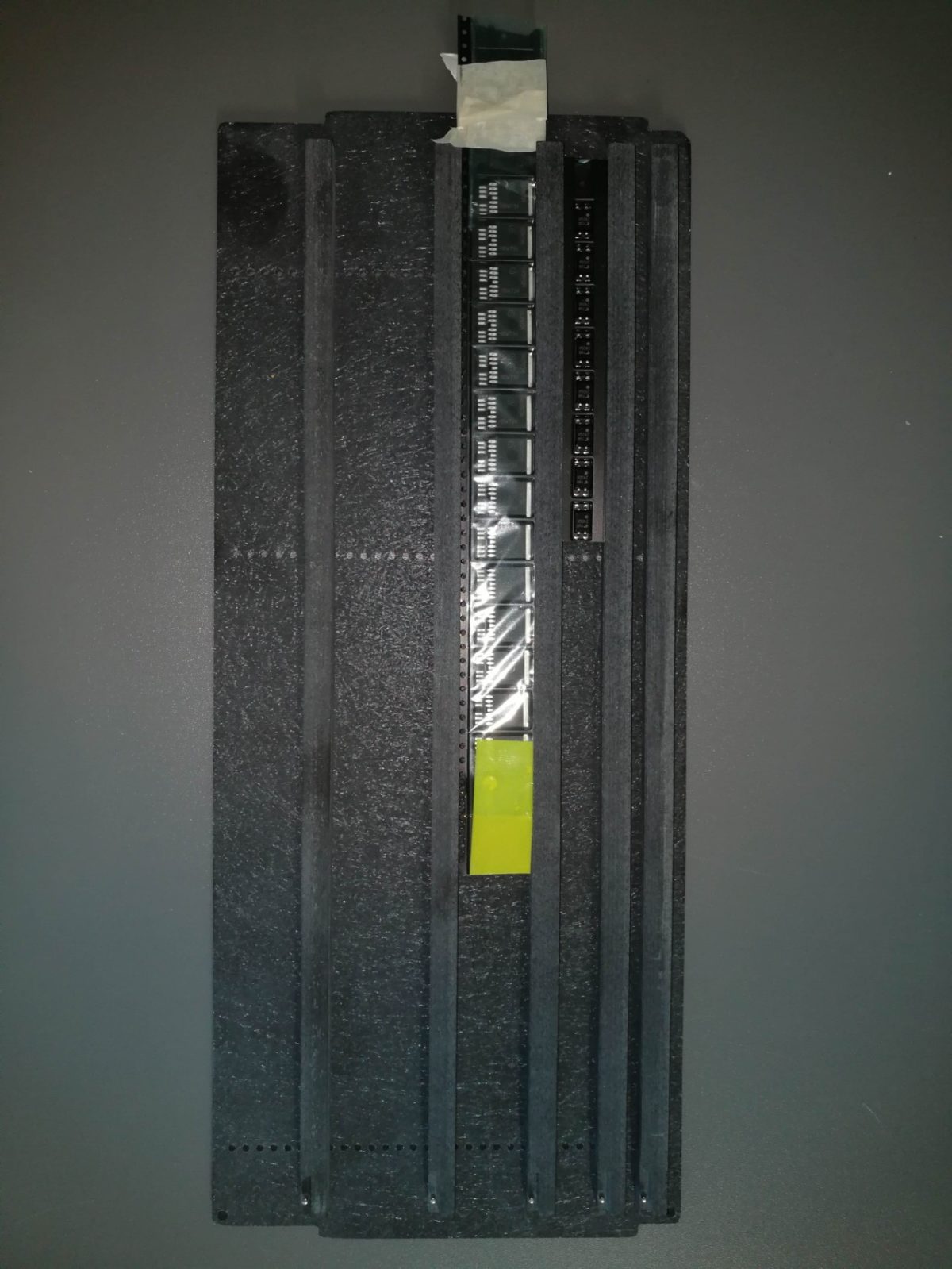
Small and lightweight components sometimes bounce inside the tape causing them to be placed upside down or on the side. (This happens a lot with 0603 and 0402 resistors). This is caused by a height difference of the different feeders. Although the pick height can be adjusted in the software it is often difficult and time consuming to adjust the correct height for each feeder. To mitigate this problem the tape can be installed like in the picture below. This improves the pick up and reduces the amount if misplaced parts.
It is important to adjust the small screwed plate as close to the peeled part as possible to prevent mispicks. If you place the tape behind the golden plate several parts will be already exposed without any guidance and they will most probably bounce if the height is not 100% correctly set. The peeler can also cause the parts to bounce. So for lightweight parts it’s best to use a smaller peel strength. (around 40 or 50 worked well fo me). It is important to use the small hinge on the back of the feeder. If the tape goes into the peel box in a straight line the pick and place head can collide with the tape and loose parts.
The placing accuracy is sufficient to place 0603 or even 0402 resistors. Although the manufacturer claims it can place 0201 parts I would strongly advise against this endeavour. The accuracy itself is sufficient but the reliability of the feeders is lacking.
In the picture below you can see correctly placed 0603/0805 parts. The parts are placed on the sticky tape they provided.
If possible, all parts should be ordered on a reel or on a continuous strip of tape. For some parts e.g. expensive microcontrollers it doesn’t make sense to order them on a DigiReel because the DigiReels are rather tight and can cause jams. It is easier to attach a 30cm long tape to make it easier to install. Bigger parts can also be ordered on a tray. Never order parts as single pieces.
I had really good experience with the adjustable tray where cut tape can be inserted. If i have expensive parts or parts that cause problems with the feeder i usually put them in the adjustable feeder. So far i have been very happy with it.
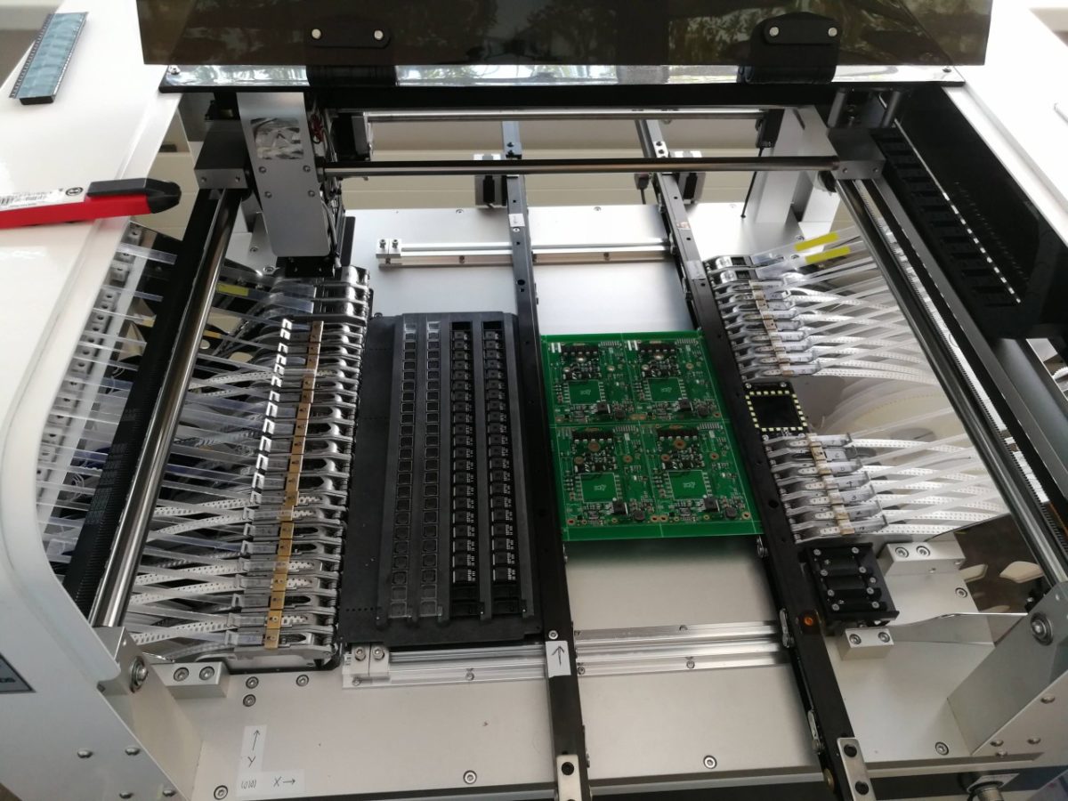
I haven’t used the vibration feeder so I can’t comment on that. Below is a video of panels being assembled. The assembly per panel (600 parts per PCB) took around 12 minutes which results in about 3000parts per hour with vision. I had to do manual correction on about 15% of the boards which was mainly caused by improper programming/parts bouncing off the PCB because the place height wasn’t set correctly. In the end of the video you can see a screwdriver and pliers attached to the tape. With some reels it can happen that the peeler “eats” the peeled tape. With a bit of additional weight it doesn’t happen anymore.
[embedyt] https://www.youtube.com/watch?v=j_63KfJ_-Tc [/embedyt]So far I have assembled hundreds of boards with the machine an it is still going strong. Actually most of the problems of my finished boards were caused by bad soldering due to incorrectly applied solder paste but that’s a whole different story.
In the end I am quite happy with the machine as it’s certainly a decent bang for buck.
We are also using this machine, what is your results when placing QFTP components?
We find that 2 sides are perfectly placed, but the other two are slightly angled, so it looks as if it is more on edge of the pad instead of the centre.
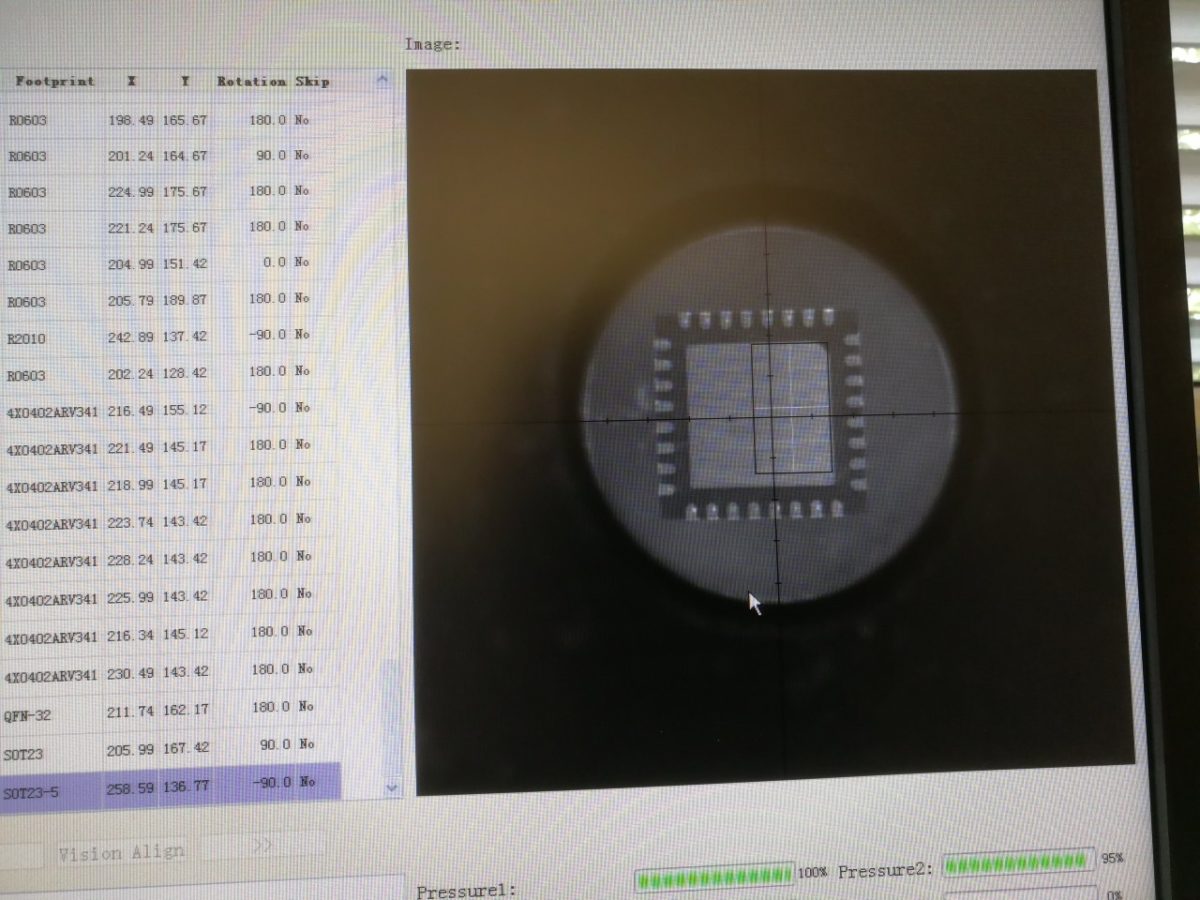
I haven’t placed many TQFP so can’t really tell. My machine often had problems with QFNs that had a center pad… for some reason it always put it at an angle of few degrees. (that was a 32pin 5×5 qfn package) also something that I noticed was the incredible sensitivity to ambiant light. In the end I put some cardboard onto the machine to reduce the ambient light and it worked a bit better but it was still unreliable for some packages.
Thanks for this useful review. Considering the Neoden 4 as well. Can you please comment on their (software) upgrade philosophy over the past years? Thanks!
I haven’t worked at the company where I used the Neoden4 for quite a few years so I can’t comment on that. But during the time I used the machine I never got an update, so I wouldn’t count on it.
thanks , this really works for me
Is that a original feeders?
I have the N4 without the gold plates.
All feeders were original.
“…machine can’t be properly screwed to the stand because the two hole on one side are off by about 1cm.”
You have the unit mounted wrong on the stand. You need to rotate the stand 90 degrees so that it looks like a “T” when you stand in front of the machine. The narrow part of the stand should only be visible when you stand in front of the machine.